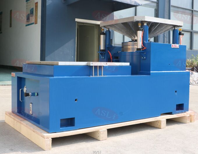
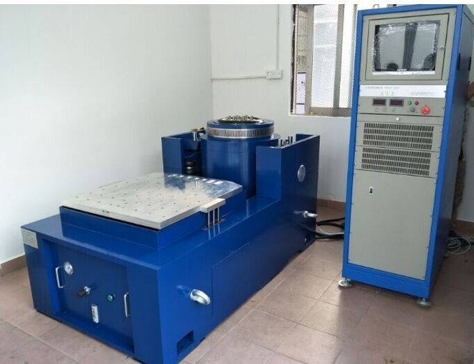
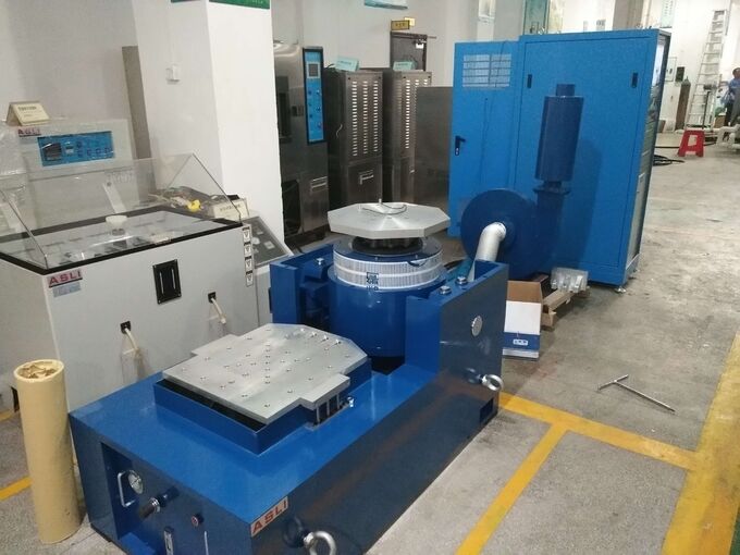
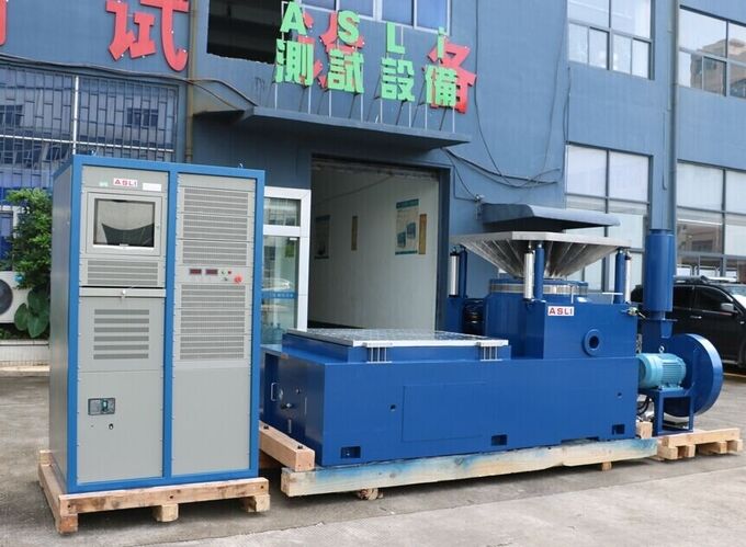
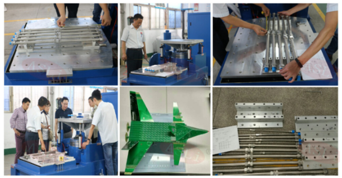
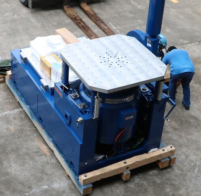
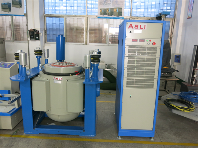
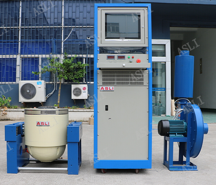
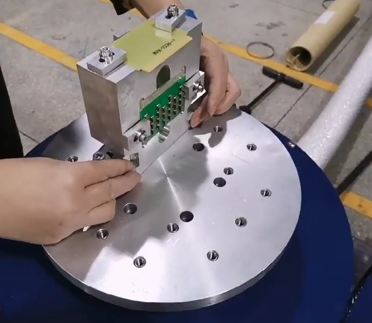
A PCB vibration test bench is designed to simulate the vibrations that a PCB might experience during its operation. The test bench typically consists of a base plate, on which the PCB is mounted, and a vibration generator that produces vibrations of different frequencies and amplitudes. The vibration generator can be either an electrodynamic shaker, like our model type ES-3.
| Model | Rated Sine Force (N) |
Rated Random Force (N) |
Frequency Range (Hz) |
Rated Acceleration (m/s²) |
Rated Speed (m/s) |
Rated Displacement (p-p) mm |
Max. Loading (kg) |
Moving Coil (kg) |
Dimension of Moving Coil (mm) |
|---|---|---|---|---|---|---|---|---|---|
| ES-3 | 3000 | 3000 | 3-3500 | 1000 | 1.6 | 25 | 100 | 3.5 | Φ150 |
| ES-3a | 3000 | 3000 | 3-3500 | 400 | 1.6 | 40 | 120 | 9 | Φ230 |
| ES-6 | 6000 | 6000 | 3-3500 | 1000 | 1.6 | 25 | 180 | 6.5 | Φ230 |
| ES-6a | 6000 | 6000 | 3-3500 | 1000 | 1.6 | 51 | 250 | 12 | Φ230 |
| ES-10 | 10000 | 10000 | 3-3000 | 1000 | 1.8 | 51 | 270 | 14 | Φ240 |
| ES-20 | 20000 | 20000 | 3-3000 | 1000 | 1.8 | 51 | 300 | 30 | Φ320 |
| ES-30 | 30000 | 30000 | 3-2800 | 1000 | 1.8 | 51 | 450 | 40 | Φ450 |
| ES-40 | 40000 | 40000 | 3-2800 | 1000 | 1.8 | 51 | 500 | 50 | Φ450 |
| ES-50 | 50000 | 50000 | 3-2700 | 1000 | 1.8 | 51 | 750 | 50 | Φ450 |
| ES-60 | 60000 | 60000 | 3-2700 | 1000 | 1.8 | 51 | 750 | 60 | Φ450 |
| ES-100 | 100000 | 100000 | 3-2500 | 1000 | 1.8 | 51 | 1000 | 90 | Φ450 |
| Model | Bench Size (mm) | Frequency Range (Hz) | Weight of Moving Parts (kg) |
|---|---|---|---|
| LT0303 | 300×300×22 | 5-1000 | 6.6 |
| LT0303 | 300×300×26 | 5-1500 | 7.8 |
| LT0303 | 300×300×30 | 5-2000 | 9.0 |
| LT0404 | 400×400×22 | 5-1000 | 11.2 |
| LT0404 | 400×400×26 | 5-1400 | 13.2 |
| LT0404 | 400×400×30 | 5-2000 | 16.0 |
| LT0505 | 500×500×25 | 5-1000 | 19.3 |
| LT0505 | 500×500×30 | 5-1500 | 23.1 |
| LT0505 | 500×500×35 | 5-2000 | 27.0 |
| LT0606 | 600×600×25 | 5-1000 | 27.5 |
| LT0606 | 600×600×30 | 5-1200 | 33.0 |
| LT0606 | 600×600×40 | 5-2000 | 45 |
| LT0707 | 700×700×25 | 5-800 | 36.8 |
| LT0707 | 700×700×30 | 5-1000 | 44.2 |
| LT0707 | 700×700×35 | 5-1500 | 52 |
| Model | Weight (kg) | Max. Frequency (Hz) | Bench Size |
|---|---|---|---|
| VT300 | 10 | 2000 | Φ300 |
| VT400 | 16 | 2000 | Φ400 |
| VT500 | 25 | 1500 | Φ500 |
| VT600 | 35 | 1000 | Φ600 |
| VT0303 | 15 | 2000 | 300×300 |
| VT0404 | 22 | 1500 | 400×400 |
| VT0505 | 30 | 500 | 500×500 |
| VT0606 | 58 | 350 | 600×600 |
| VT0808 | 140 | 350 | 800×800 |
| VT1010 | 180 | 350 | 1000×1000 |
| VT1212 | 250 | 350 | 1200×1200 |
| VT1212 (Round) | 220 | 350 | Φ1200 |
A Printed Circuit Board (PCB) is a vital component in many electronic devices. PCBs are designed to withstand various environmental conditions, including vibration. PCB vibration test benches are used to test the durability and reliability of PCBs in these environments.
During the test, the PCB is subjected to a series of vibration cycles of different frequencies and amplitudes. The vibration is applied in different directions, including vertical, horizontal, and rotational directions, to simulate real-world scenarios. The vibration generator is typically controlled by a computer system that can adjust the amplitude and frequency of the vibration.
Method 514 of MIL-STD-810G defines vibration test procedures that replicate the mechanical environments equipment experiences during transportation and service. It is widely referenced by defense contractors, automotive suppliers, and electronics manufacturers to qualify PCBs and electronic assemblies for field reliability.
Our shaker system executes the three primary procedures defined in Method 514, with pre-loaded profiles and user-adjustable parameters to match your specific PCB and acceptance criteria.
Baseline qualification for PCBs transported by wheeled vehicles, tracked vehicles, or aircraft. Sine and random profiles matched to exposure category.
Simulation of unrestrained cargo vibration during transport. Used for packaged PCBs, loose components, and shipping-container qualification.
Low-frequency, high-displacement vibration typical of large assemblies transported on wheeled or tracked vehicles.
Every component is matched and calibrated as a complete system — eliminating integration risk and reducing commissioning time on your lab floor.
Air-cooled, lightweight armature with high first-order resonance.
Switching-type, over 90% efficiency, low-distortion output.
DSP closed-loop control with sine, random, shock, and RSTD modes.
Custom or standard interface plates matched to your PCB footprint.
Low-noise blower designed for continuous operation.
Close-up views of key components — armature, expander interface, controller cabinet, and installation details.


High-resolution photos and dimensional drawings are available on request.
What it means for you: Detects resonance points and weak solder joints on PCB assemblies before they reach the field — reducing warranty claims and field failures.
What it means for you: Delivers repeatable, standard-compliant waveforms across multiple runs — critical for audit-grade reporting and cross-lab comparison of PCB test results.
What it means for you: Interface plates designed to match your PCB footprint, from small SMT modules to large backplanes — no need for a second test bench.
What it means for you: Start PCB qualification tests on installation day with pre-loaded profiles for common vibration standards, reducing commissioning time.
Send your PCB dimensions, weight, and test standard. Our engineering team will reply with a recommended model and fixture solution within one business day.