Thermal Testing Standards for Flexible Printed Circuit Boards (FPCs)
Thermal Stress in Flexible PCBs
Flexible printed circuit boards (FPCs) often experience thermal stresses due to differences in the coefficient of thermal expansion (CTE) between polyimide substrates and conductive traces. These stresses can cause:
*Cracks or delamination of conductive layers
*Accelerated material degradation under prolonged heat
*Shortened component lifespan and risk of electrical failure
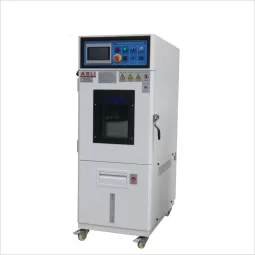
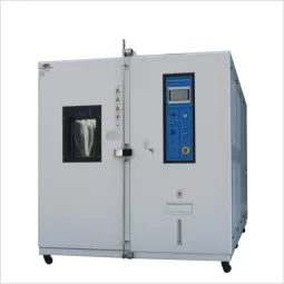
To evaluate whether a flexible PCB can withstand such conditions, two major tests are used: thermal cycling and thermal shock testing.
1. Thermal Cycle Test
This test evaluates the ability of FPCs to endure repeated thermal expansion and contraction.
*Typical range: -40 °C to +125 °C
*Failure modes detected: microcracking, oxidation, embrittlement, and fatigue-related electrical failures
*Purpose: assess long-term durability in fluctuating operating environments
2. Thermal Shock Test
This test measures a PCB’s resilience to rapid temperature transitions.
*IPC-TM-650 2.6.7 Requirements:
Temperature range: -55 °C up to Tg (glass transition temperature) or 210 °C
Reflow simulation followed by 100 rapid thermal shocks
Acceptance criteria: resistance change < 5%
*MIL-STD-202G Method 107:
Defines both air-to-air and liquid-to-liquid shock methods
Air-to-air: DUT moves between hot and cold chambers; slower transitions mimic real-world operation
Liquid-to-liquid: DUT rapidly transferred between temperature-controlled liquids; fast transitions simulate extreme stress
Temperature ranges:
Air-to-air: -65 °C to +500 °C
Liquid-to-liquid: -65 °C to +200 °C
These tests reveal failure modes such as solder joint fracture, through-hole cracking, and delamination.
3. Aging Test
Aging tests evaluate long-term performance under prolonged thermal or electrical stress.
Static aging: high voltage and temperature applied without signals; focuses on storage reliability
Dynamic aging: stress applied while circuits are active; identifies weak points in complex assemblies
Test conditions: up to 125 °C for 40–160 hours
4. Mechanical Stress Testing
In addition to thermal testing, flexible PCBs undergo mechanical stress evaluations:
Bending tests: repeated flexing cycles to confirm mechanical durability
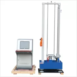
Vibration tests: simulate shocks and vibrations during transport or operation
Tensile tests: measure solder joint strength and adhesion of mounted components
Why These Tests Matter
Thermal and mechanical stress tests are essential for ensuring that flexible PCBs can withstand real-world operating environments. From aerospace to automotive and defense applications, these tests validate product durability before deployment.


